I have, obviously, started with an idea. I didn't like any of the exisiting smart lamp solutions, mostly because they lacked customizability. So my thought process was to start with some minimal requirements. I have come up with the following:
- RGB LED Strip for the actual light
- Bluetooth for controls
- Some sort of Arduino to process it all
Choosing the RGB LED Strip
There are lots of different options, there are single-color strips, RGB strips or programmable strips, where you can change the color of every single LED. I though I would be fine with just controlling the color of the entire strip so I went with something like this.
I don't need the stupid IR controller, but I found that sometimes you can get the same thing with the controller for less than without it. The key characteristics are:
- SMD 5050 - this represents the size of a single LED
- 60 LED/m - I want this to be bright
- 12V DC - operating voltage
- 1A/m - required current per 1 meter of the strip
These things are really key, because everything else in the system is based on these values. If you change anything, be sure to adjust the rest of the system accordingly.
Next, Arduino
I have come across RFduino. I have bought some basic kit when they were on Kickstarter, but I have since bought 6 more units. The trouble with this board is a bit in its availability. Sparkfun has it, but in the EU it is much more difficult to get your hands on it. I ended up buying from Mouser, but they are primarily a wholesale operation, so it's expensive to buy small quantities from them.
Having said that, I'm really happy with RFduino, it is programmable with the Arduino IDE, has nice sample code and iOS libraries, uses Bluetooth 4.0 Low Energy, which is super nice and, most importantly, I have found the connectivity great, it just always works. It has also survived a couple of blunders on my part, such as connecting it to 5V power instead of the recommended 3.3V.
Power supply
So my calculation went like this: I want a 1m long LED strip controlled by RFduino, that is 12V * 1A = 12W. So I need a 12W power supply. I ended up buying this one because it has enough power, nice connector and is relatively cheap.
Connecting it all together
Now I have a LED strip and a power supply which both operate at 12V, but I have a RFduino which operates at 3.3V. So the problem is twofold:
- Convert 12V to 3.3V to power the RFduino
- Drive the 12V LED with the signal from RFduino
This in the end translates into 2 subsystems that need to be designed. A power regulator circuit to power RFduino from 12V and an amplifier or a relay that could drive the LEDs.
Voltage Regulator for the RFduino 12V to 3V
This was the hardest part to figure out for me. I didn't want anything overly complicated and in the end I've settled for the LP2950-33 (Datasheet). It looks like a transistor, has 3 legs, one for input, one for output and one for ground. The usual usage example I found involved capacitors between output and ground and optionally between input and ground to further stabilize the voltage. LP2950 comes in different varietes, so I chose the one that had it's output voltage closest to RFduino's 3V.
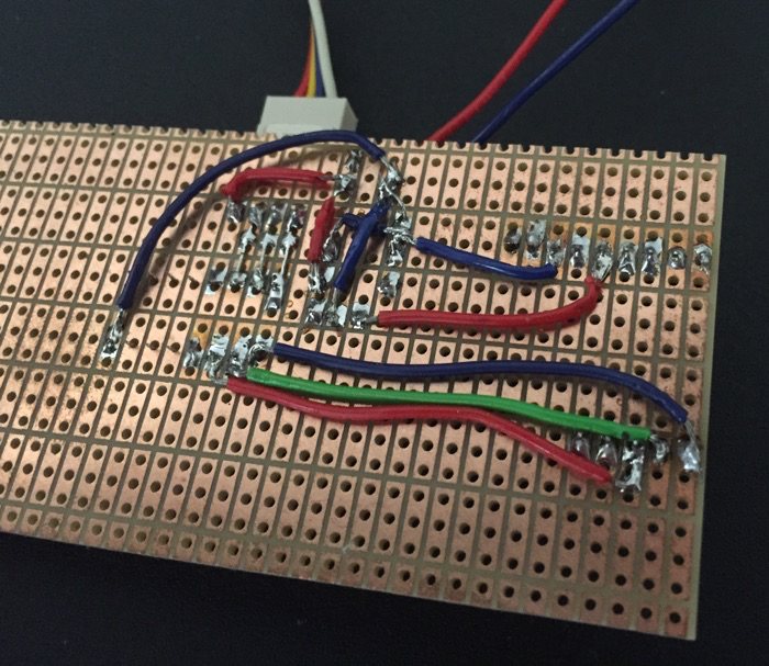
Darlington Array to drive the LED Strip
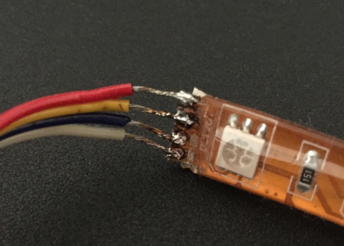
The last thing to do was to bring the PWM pin output from RFduino into the strip. The way the strip is connected is that there is a +12V cable and three different grounds, one for each of the RGB channels. So basically what the darlington does, is connect each of the RGB channels to the ground such, that the amount of current flowing through them can be controlled by RFduino.
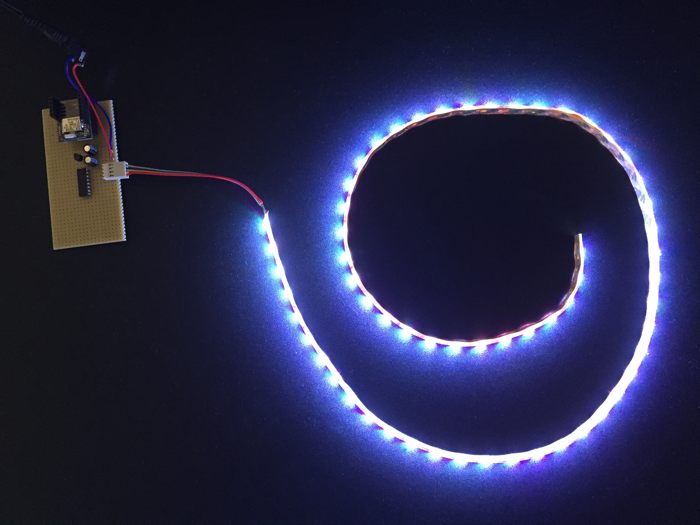
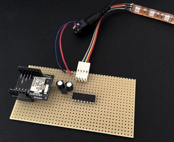
The Prototype
I have built the prototype using an universal board with headers bought from Aliexpress so that I can plug the RFduino in and out as I please. This is what it looks like when I turn it on: