Design Tool
I haven't really searched all that far to discover Eagle CAD, it seems to be probably the most widely used software for PCB design. I have watched two tutorial videos on YouTube by Jeremy Blum, Schematic Design and Printed Circuit Board Layout. That gave me a pretty good idea about how to use the software. I won't pretend there weren't any issues, but all were successfully resolved with a search on StackOverflow. Overall I think it is a very good tool. I've never used it before but I have been able to do all I wanted from it in maybe an hour.
Schematic Design
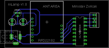
I started out with a schematic design. I already had a working prototype of the lamp, so it wasn't so hard to use that to start things off. Overall the schematic is divided into three sub-circuits from the left:
- Power, voltage dropdown for the RFduino
- The RFduino
- Darlington Array to increase the voltage back
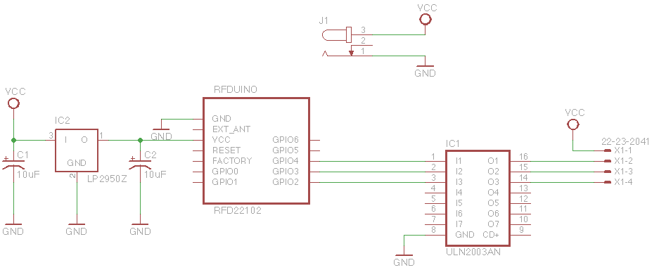
The most problematic part of the voltage regulator was to actually obtain the part I chose: LP2950-33. Ideally you would choose a LP2950-30 here, as RFduino's reference voltage is 3.0V, but it is rated to up to 3.6V, so 3.3V is fine. I have, by accident supplied it with more than that (think ~5V) and it has surprisingly survived.
I have used two 10μF capacitors, one at input and one at output to further stabilize the voltage.
The RFduino is pretty self-explanatory, I have hooked the VCC and GND pins and I've connected the GPIO pins 2, 3 and 4 to the input of the darlington array.
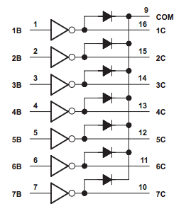
The last part was the Darlington Array. If you take a look at the schematic below, you'll see how it's wired inside. The LED strip has one positive wire and then three ground wires, each for one of the RGB colors. The positive end is connected directly to VCC, 1B-3B are connected to the output of the RFduino, 1C-3C are connected to the LED strip and the ground (not shown in the little schematic) is connected to the circuit ground.
One of the biggest issues I had was to find the parts, Eagle has a large database of components, but still, things like RFduino are not there. Also I needed to make sure I can eventually buy the things somewhere.
Board Design
After finishing the schematic, I proceeded with the board design. First I have tried to automatically layout the components, but Eagle has made a complete mess of things, so in the end I had to lay out everyting myself anyway. The process can get a bit awkward with the bends of the wires, but if it does, you can just delete the wire and do it again. You can set the widths of the wires, so I've chosen slightly thicker wires for the 12V lines and slightly thinner for the rest. I've also managed to keep all the connections to the one side of the board, which just makes it look better in my opinion.
Manufacturing
Somewhere on the internet I have found OSH Park a company from USA that will make PCBs from Eagle CAD files: 3 copies of the board for $5 per square inch (imperial, really??) and ship it anywhere in the world for free. My board cost me under $20, I have ordered it on Feb 26, it got shipped on Mar 6 and arrived in Prague on Mar 18. This manufacturing delay makes mistakes super expensive, but luckily the board works as designed.
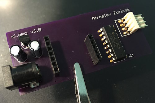
Assembly
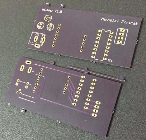
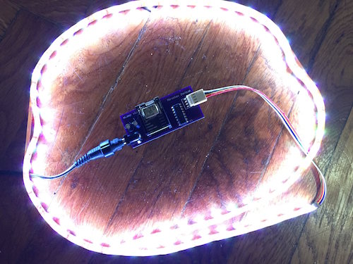
I have assembled the components onto the board today, it took me about an hour and was a really pleasant experience. And the fact that it has worked on the first try was really satisfying. Here have a look at the finished product.
Final Notes
OSH Park has good guidelines to follow (they also have a file that you can import to Eagle that will check your design). I suggest reading those before submitting anything.
The boards that have arrived look stunning, but there are a couple of things I noticed that could be improved:
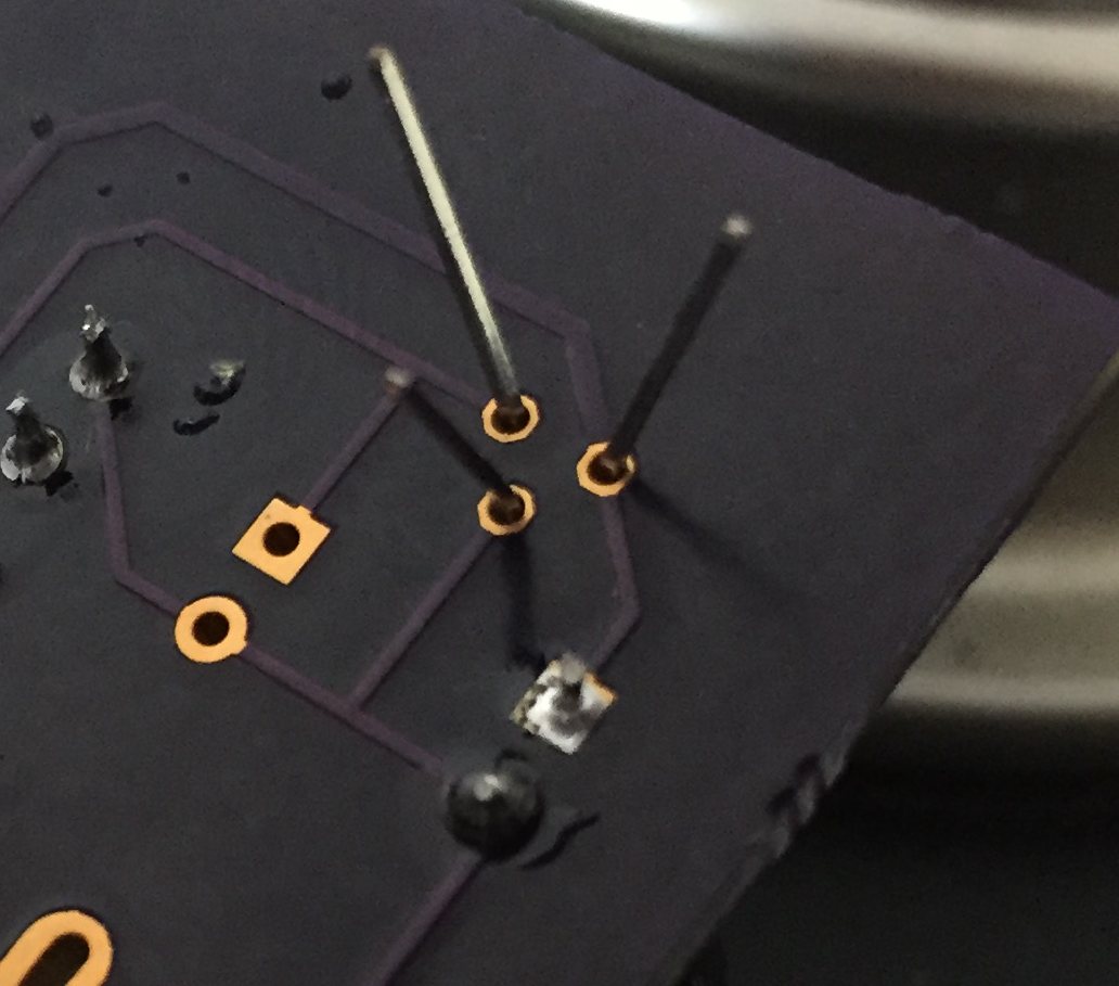
- Some joints don't have the small metal area surrounding the hole, which makes them slightly more difficult to solder (see the holes for RFduino and the voltage regulator)
- The other joints have the metal area around holes on both sides of the board, even though only one side has wires
- The boards had some rough edges around the places where they were broken apart from the panel that had to be sanded, but this is just a minor issue
Most of these are my fault, I will try to fix them next time I have boards printed.